Surface mount technology vs through hole is a key decision in PCB design because it affects board size, component strength, assembly process, cost, inspection and long-term reliability. Surface mount technology places components directly on PCB pads, while through-hole technology inserts component leads into drilled and plated holes before soldering. For many modern products, SMT is preferred for compact, high-density and automated assembly. Through-hole technology is still valuable for connectors, transformers, terminals, relays, high-power parts and components exposed to mechanical stress.
What Are Surface Mount Technology and Through-Hole Technology?
Surface mount technology and through-hole technology are two PCB assembly methods that define how electronic components are mechanically and electrically connected to a printed circuit board.
In SMT, components such as resistors, capacitors, ICs, LEDs and sensors are mounted onto copper pads on the PCB surface. Solder paste is printed on the pads, components are placed by pick-and-place machines, and the board is heated in a reflow oven to form solder joints. SMT is widely used because it supports smaller packages, double-sided placement and automated high-volume production. This level of automation becomes especially important when a project moves toward high volume pcb fabrication, where PCB panel design, component placement efficiency and consistent production quality must be considered together. The overview of surface-mount technology published by Wikipedia also explains that SMT enables components to be mounted directly onto PCB surfaces and supports greater production automation and component density.
In through-hole technology, component leads pass through plated holes and are soldered on the opposite side or inside the barrel of the hole. This creates strong mechanical anchoring, which is why through-hole parts are common for connectors, heavy components and high-stress interfaces. IPC lists both through-hole technology and surface mount technology as major inspection and training areas within IPC-A-610 assembly acceptability guidance.
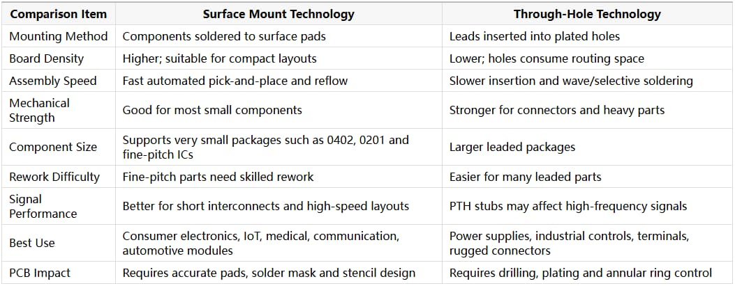
Surface Mount Technology vs Through Hole Comparison Table
Surface mount technology and through-hole technology should be compared by density, strength, assembly speed, cost, inspection and product application.
For bare-board quality, IPC-A-600 is widely recognized for printed board workmanship, while IPC-A-610 is widely used for electronic assembly acceptability. The official IPC-A-610 Acceptability of Electronics Assemblies program covers soldering requirements for plated-through holes, surface-mount component criteria, solder fillet dimensions and common assembly defects such as tombstoning, dewetting and voiding. Buyers should define the required IPC class, assembly standard and inspection criteria before production, especially for industrial, automotive or medical projects.
How SMT and Through Hole Affect PCB Design
SMT and through-hole choices affect PCB layout because pads, drilled holes, routing space, thermal relief, solder mask openings and assembly sequence must be designed differently. SMT designs require accurate land patterns, solder mask expansion, paste stencil control and component spacing for automated placement. Fine-pitch ICs may require controlled solder paste volume and good solder mask registration. For high-speed boards, SMT can reduce parasitic inductance because component leads are shorter.
Through-hole designs require drilled and plated holes, annular rings, clearances, lead length control and proper solder filling. Holes can block inner-layer routing and reduce available space, especially in dense multilayer boards. During 4 layer pcb fabrication, through holes may pass across multiple copper and dielectric layers, so drill diameter, annular ring size and routing clearance should be defined early in the layout. HUIHE Circuits’ multilayer PCB examples show common fine trace and space capabilities such as 4/4 mil, 5/4 mil and 7/4 mil, which can support compact routing when the board is designed with manufacturability in mind.
For high-speed or RF-related boards, designers should also consider impedance control. HUIHE Circuits provides impedance control PCB manufacturing, and its capability page states impedance tolerance can reach ≤±5% for suitable high-speed and communication applications.
When Should You Choose SMT, Through Hole or Mixed Assembly?
Choosing SMT, through hole or mixed assembly means matching the component package and PCB structure to electrical performance, mechanical load, production volume and reliability requirements.
Choose SMT when the project needs compact size, automated production, lighter weight, high component count or double-sided assembly. It is usually the better choice for communication devices, IoT products, medical electronics, control modules and consumer electronics. For example, a compact medical circuit board may use SMT to accommodate dense sensor, control and signal-processing components while retaining selected through-hole connectors where stronger mechanical support is required.
Choose through hole when the component must handle high mechanical stress, frequent plugging and unplugging, high current, heat dissipation or heavy body weight. Connectors, terminal blocks, transformers, electrolytic capacitors and relays often remain through-hole parts for reliability reasons.
Mixed assembly is common in real products. A board may use SMT for ICs and passive components while keeping through-hole connectors or power components. IPC’s board design standards are useful references for designers who need to align layout choices with manufacturable assembly and fabrication requirements. HUIHE Circuits helps buyers evaluate PCB material, copper thickness, via structure, surface finish and through-hole requirements before production.
Conclusion
Surface mount technology is best for compact, high-density and automated PCB assembly, while through-hole technology remains important for mechanical strength, high-stress connectors and some power components. The best design is often not purely SMT or purely through hole, but a balanced PCB layout that uses each method where it performs best. For buyers, the decision should be made before PCB fabrication, not after assembly quoting. Pad design, hole size, annular ring, solder mask, surface finish, panelization and inspection requirements all affect final yield. HUIHE Circuits supports multilayer PCB, impedance control PCB and through-hole PCB manufacturing for customers who need reliable boards for industrial, medical, communication, automotive and consumer electronics applications.
FAQ
1.What is the main difference between SMT and through hole?
SMT components are soldered directly to surface pads, while through-hole components have leads inserted into plated holes and soldered to the PCB.
2. Is SMT cheaper than through hole?
SMT is often more cost-effective in medium- and high-volume production because it supports automated placement and reflow soldering, but tooling, stencil and inspection requirements still matter.
3. Is through hole stronger than SMT?
Through-hole mounting usually provides stronger mechanical anchoring, making it suitable for connectors, terminals and heavy components exposed to stress.
4. Can one PCB use both SMT and through-hole components?
Yes. Mixed assembly is common. Many boards use SMT for small components and ICs, while using through-hole parts for connectors, power devices or mechanical support.
5. Which technology is better for high-speed PCB design?
SMT is generally better for high-speed designs because it supports shorter interconnects and smaller parasitic effects. However, stackup, impedance control and routing design are also critical.
6. Why choose HUIHE Circuits for SMT and through-hole PCB projects?
HUIHE Circuits provides multilayer PCB, impedance control PCB, half-hole and through-hole PCB manufacturing support, helping buyers design boards that are easier to fabricate, assemble and inspect.
Leave A Comment